Synchronizing Data Output with an External System
In this example, we'll show how to synchronize data output to an external device via a GPIO input. The output data will interpolated as if it were sampled at the falling edge of the input signal.
We'll stream Delta Theta (0x80,0x07) and Delta Velocity (0x80,0x08) from the Sensor Data set and Euler Angles (0x82,0x05) from the Filter Data set, as well as the Event Source (0xFF,0xD0), Reference Timestamp (0xFF,0xD5), and Reference Time Delta (0xFF,0xD6) for each.
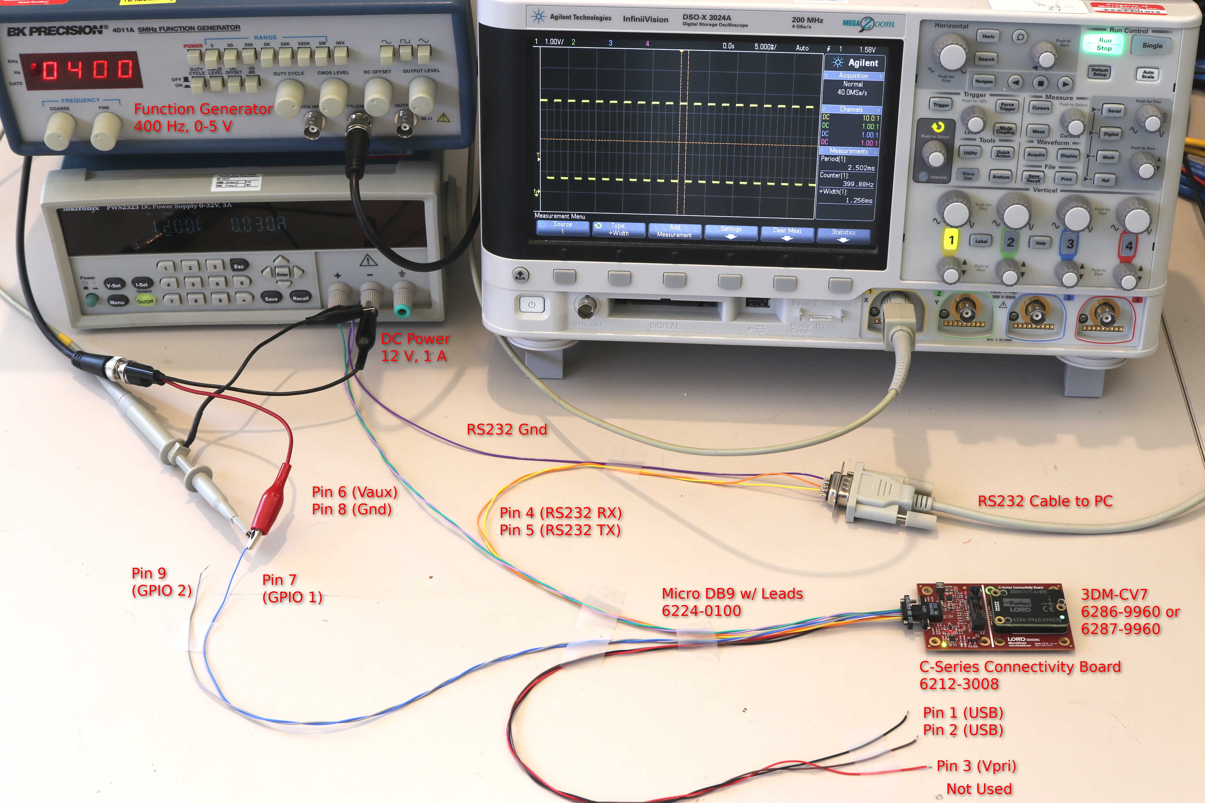
Hardware Setup
For this example, a function generator will be used to provide a timing signal. Set the output voltage for 0 to 3 volts and the output frequency to 400 Hz. Leave the output disabled for now.
Alternatively, a push button or other input may be used. Connect the button between GPIO 1 and ground, so that it pulls the pin low when pressed (for normally-open buttons).
GPIO Setup
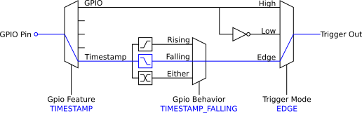
In this example, we'll use GPIO 1 as the sync input. We need to configure the pin for hardware timestamps with the internal pullup enabled. The internal pullup will pull the pin to a default high state when left disconnected. The pullup is not necessary when the input will be actively driven, such as with a function generator. We use it in this example so a push button can be used. Similarly, we'll use the falling edge as that will coincide with normally-open push button presses (rising edges will occur when the button is released).
Command: GPIO Configuration (0x0C,0x41)
- Function: WRITE (0x01)
- Pin: 1
- Feature: TIMESTAMP (0x04)
- Behavior: TIMESTAMP_FALLING (0x02)
- Mode: pullup (0x04)
Command bytes: 0101040204
MIP Packet: 75650c07 07410101040204 4171
Inspection with a multimeter or oscilloscope will show that the voltage at GPIO 1 is hovering around 3 volts.
Event Trigger
We'll create a Trigger: GPIO set for EDGE mode on GPIO 1.
Command: Event Trigger Configuration (0x0C,0x2E)
- Function: WRITE (0x01)
- Instance: 1
- Type: GPIO (0x01)
- Parameters:
- Pin: 1
- Mode: EDGE (0x04)
Command bytes: 0101010104
MIP Packet: 75650c07 072e0101010104 2af4
This trigger will activate for one event cycle each time GPIO 1 transitions from high to low.
Message Action
To output data, we need one Action: Message per descriptor set and data rate. We'll set one up for the sensor data and one for the filter data.
Command: Event Action Configuration (0x0C,0x2F)
- Function: WRITE (0x01)
- Instance: 1
- Trigger: 1 (this must match the trigger set up previously)
- Type: MESSAGE (0x02)
- Parameters:
- Descriptor Set: Sensor Data (0x80)
- Decimation: 0 (oneshot)
- Number of Fields: 5
- Descriptors: [0xD0 (Event Source), 0xD5 (Reference Timestamp), 0xD6 (Delta Ref Time), 0x07 (Delta Theta), 0x08 (Delta Velocity)]
Command bytes: 0101010280000005d0d5d60708
MIP Packet: 75650c0f 0f2f0101010280000005d0d5d60708 47ca
Command: Event Action Configuration (0x0C,0x2F)
- Function: WRITE (0x01)
- Instance: 2 (this must be different from the first message action)
- Trigger: 1 (this must match the trigger set up previously)
- Type: MESSAGE (0x02)
- Parameters:
- Descriptor Set: Filter Data (0x82)
- Decimation: 0 (oneshot)
- Number of Fields: 4
- Descriptors: [0xD0 (Event Source), 0xD5 (Reference Timestamp), 0xD6 (Delta Ref Time), 0x05 (Euler Angles)]
Command bytes: 0102010282000004d0d5d605
MIP Packet: 75650c0e 0e2f0102010282000004d0d5d605 3d7a
Enable and Test
Now that everything has been configured, we must enable the trigger and input signal.
Command: Event Control (0x0C,0x2B)
- Function: WRITE (0x01)
- Instance: 1 (same as the trigger above)
- Mode: ENABLED (0x01)
Command bytes: 010101
MIP Packet: 75650c05 052b010101 1e82
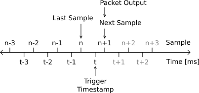
Enable the function generator now. The device will begin streaming two packets, one with the Sensor Data descriptor set (0x80) and one with the Filter Data descriptor set (0x82), at 400 Hz. The timestamps of each packet will reflect the exact time that the input signal changed from high to low. Both packets will have the same timestamp and event source. The delta time field of each will be 2.5 ms, or 1/400th of a second.
If using a push button, one of each type of packet will be emitted per push, assuming the button contacts do not bounce. If the button is pressed about once per second, the delta time fields will reflect this.
Note: Data is timestamped at the GPIO input signal edge and linearly interpolated to capture the sensed motion at that instance. However, the data is sent at intervals determined by the 3DM-CV7's internal clock.